Labs & Infrastructure
Professor In-charge:
Dr. Ravi Ranjan
Scope of the Course and its objective
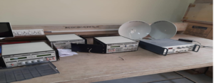
The purpose of this lab is to give the student an understanding of difference between Analog and Digital modulation techniques with their implementation and the Analog Modulation and Demodulation techniques in different Application.
Course Outcomes:
CO1: Able to understand different baseband modulation and demodulation techniques.
CO2: Develop experiment on different passband modulation and demodulation techniques.
CO3: Understand the basic of MATLAB and its Communication tools.
CO4: Apply appropriate techniques to solve communication system problem.
CO5: Able to develop new experiment in the field of communications and able to Prepare and deliver an oral presentation on this
| S. No. | Experiment Detail |
| 1. | Study of CRO and Function Generator. |
| 2 | Generation of AM signals using base/collector modulation and in coherent detection/envelope detection/diode peak detection of AM signals (DSB with carrier). |
| 3. | To verify amplitude modulation and demodulation and to calculate the modulation index of an AM modulated wave. |
| 4. | Study of AM receiver stage and checking its waveform in CRO. |
| 5. | To simulate Amplitude modulation and demodulation using MATLAB. |
| 6. | To simulate generation of FM using MATLAB. |
| 7. | To simulate Frequency modulation and demodulation using MATLAB. |
| 8. | Study of pulse width modulation (PWM) and its demodulation. |
| 9. | To simulate Pulse width modulation (PWM) modulation and demodulation using MATLAB. |
| 10. | Study of pulse amplitude modulation (PAM) and its demodulation. |
| 11. | Study of pulse position modulation (PPM) and its demodulation. |
| 12. | Study the data formatting and carrier modulation using ST2156 Kit |
| 13. | Study the carrier demodulation and data Reformatting and using ST2157 Kit |
| 14. | To setup a communication link between uplink transmitter and downlink receiver using Satellite. |
Course Objectives:
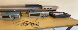
1.Understand the characteristics and features of intelligent instrumentation system.
2.Understand the functioning of OP-AMP and design OP-AMP based circuits.
3.Design of smart sensors and understand concept of data compensation,
4.Understand the process of data transfer control and Design of data converters.
Course Outcomes:
CO1: Understand the fundamental concepts of intelligent instruments and its characteristics.
CO2: Design the basic circuits using op-amp and perform operations and their troubleshooting.
CO3: Understanddifferent filters, their design and various applications in practical situations.
CO4: Design the basic building blocks of smart sensors and interfacing devices.
CO5: Analyse the basic building blocks of different types A/D and D/A converters.
List of experiments which can be performed in this lab
| S. No. | Experiment Detail
|
| 1 | Study of OP-AMP as an Inverting Amplifier and calculation of its input resistance, output resistance and gain |
| 2 | Study of OP-AMP as a Non-Inverting Amplifier and calculation of its input resistance, output resistance and gain |
| 3 | Measurement of Common Mode gain, Differential gain and CMMR of an Op-Amp-based Instrumentation Amplifier circuit |
| 4 | Design of an Integrator Op- Amp and find out its output voltage and gain by applying DC input voltage |
| 5 | Design of a Differentiator Amp and find out its output voltage and gain by applying DC input voltage |
| 6 | Study of the process of conversation of analog data into digital form by using Data Converter KIT |
| 7 | To design and verify different types of active and passive filters |
| 8 | Measurement of atmospheric temperature and pressure using various smart sensors |
| 9 | To design and verify the characteristics of various transducers |
| 10 | Study of the process of conversation of digital data into analog form by using Data Converter KIT |
Professor In-charge:
Mr. Shakti Prasad Senapati
Course Objectives:
1.Understand the characteristics of transistors.
2.Design and analyse various rectifier and amplifier circuits.
3.Design sinusoidal and non-sinusoidal oscillators.
4.Understand the functioning of OP-AMP and design OP-AMP based circuits.
Program Outcomes (POs)
PO 1: Engineering Knowledge : An ability to apply knowledge of computing and mathematics which is appropriate to computer science.
PO 2: Problem analysis:An ability to identify, formulate, and develop solutions to computational challenges.
PO 3: Design/development of solutions: An ability to design, implement, and evaluate a computational system to meet the desired soluitions of problem with feasibility.
PO 4: Conduct investigations of complex problems: Use research-based knowledge and methods including design of experiments, analysis and interpretation of data, and synthesis them to get the valid conclusions.
PO 5: Modern tool usage: An ability to use appropriate techniques, skills, and tools necessary for computing practice and makes human effort less.
PO 6: The engineer and society: An ability to analyze impacts of computing on individuals, organizations, and society.
PO 7: Environment and sustainability: Understand the impact of the professional engineering solutions on society in environmental contexts, and provide a solution for sustainable development.
PO 8: Ethics: An understanding of professional, ethical, legal, security, and social issues and responsibilities for the computing profession.
PO 9: Individual and team work: An ability to function effectively on teams to accomplish shared idea, computing design, evaluation, or implementation goals.
PO 10: Communication: An ability to communicate and engage effectively with diverse stakeholders.
PO 11: Project management and finance: An ability to apply design and development principles in the construction of software systems of varying complexity.
PO 12: Life-long learning: Recognize the need for, and have the preparation and ability to engage in independent and life-long learning in the broadest context of technological change.
Course Coordinator Name
Mr.Akhil Mohammed KK
Course Outcomes:
1.Model a practical system in transfer function form using its governing laws and apply on software like MATLAB and SIMULINK to study the performance.
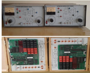
2.Apply the knowledge of control systems on practical system like AC position servo system.
3.Analyze the system response and stability in both time-domain and frequency domain on simple circuit models.
4.Design different types of compensators using time-domain and frequency domain specifications
List of experiments which can be performed in this lab
| S. No. | Experiment Detail
|
| 1. | PREDETERMINATION AND VERIFICATION OF FREQUENCY RESPONSE CHARACTERISTICS OF A LAG NETWORK |
| 2 | PREDETERMINATION AND VERIFICATION OF FREQUENCY RESPONSE CHARACTERISTICS OF LEAD NETWORK
|
| 3 | STEP RESPONSE AND FREQUENCY RESPONSE OF R-L-C CIRCUIT
|
| 4 | PERFORMANCE CHARACTERISTICS OF AN AC POSITION SERVO SYSTEM.
|
| 5 | STUDY OF MATLAB AND CONTROL SYSTEM TOOLBOX
|
| 6 | TIME AND FREQUENCY DOMAIN METHODS OF SYSTEM ANALYSIS USING MATLAB
|
| 7 | DESIGN OF PHASE LEAD COMPENSATOR IN TIME DOMAIN |
| 8 | DESIGN OF PHASE LAG COMPENSATOR IN TIME DOMAIN |
| 9 | DESIGN OF PHASE LEAD COMPENSATOR IN FREQUENCY DOMAIN |
| 10 | DESIGN OF PHASE LEAD COMPENSATOR IN FREQUENCY DOMAIN |
| 11 | FAMILIARIZATION OF SIMULINK |
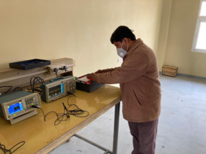
Course Objectives: -The objectives of this course are to make students capable of analysing any electrical network and to equip students with necessary tools for synthesizing electrical network for a given impedance or admittance function.
Course Outcomes: -After completion of this course student will be able to –
CO1 -Apply the knowledge of basic circuital law and simplify the electric networks
CO2 -Infer and evaluate transient response, steady state response, network functions
CO3 -Analyse two port networks
CO4 -Synthesize basic electrical networks, passive filters
List of Experiments:-
Group I- Experiments No. 1-7
Group II- Experiments No. 8-10
Group III- Experiments No. 11-12
Group IV- Experiments No. 13-14
From group (II) to (IV) one experiment from each group is compulsory and from group (I) three experiments are compulsory. Students should perform at least 10 experiments.
1.)Determination of Z parameters of a given network.
2.)Determination of Y parameters of a given network.
3.)Determination of ABCD parameters of a given network.
4.)Determination of Hybrid parameters of a given network.
5.)Series connection of two networks and determination of Z parameters of the combination.
6.)Parallel connection of two networks and determination of Y parameters of the combination.
7.)Cascade connection of two networks and determination of ABCD parameters of the combination.
8.)Plot transient response of RL circuit and verify the results with MATLAB.
9.)Plot transient response of RC circuit and verify the results with MATLAB.
10.)Plot transient response of RLC circuit and verify the results with MATLAB.
11.)Determination of amplitude response of low pass and high pass filter.
12.)Determination of amplitude response of band pass and band reject filter.
13.)Plot the impulse response of a give network using poles and zero in MATLAB.
14.)Show the effect of change in location of poles on impulse response of a network in MATLAB.
Suggested Projects: –
1)Modelling of an analogous mechanical system to an electrical system.
2)Design filter circuit for a given cut-off frequency.
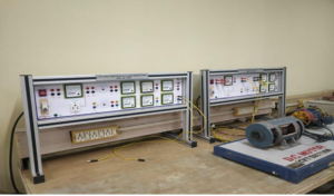
LIST OF EXPERIMENTS:
1.No load & blocked rotor tests on three phase squirrel cage induction motor.
2.Star Delta starting of three phase induction motor
3.Speed torque characteristics of three phase induction motor.
4.Load test on three phase induction motor
5.‘v’ curve and inverted ‘v’ curve of synchronous motor.
6.Voltage regulation of three phase alternator by ZPF method.
7.Determination of direct axis and quadrature axis reactance of synchronous alternator.
8.Speed torque characteristics of capacitor start type 1-ϕ induction motor.
Lab Outcomes: -After completion of this lab students will demonstrate the ability to
• Understand the differences between signal level and power level devices.
• Analyze controlled rectifier circuits.
• Analyze the operation of DC-DC choppers.
• Analyze the operation of voltage source inverters.
List of experiments
1. To Study and Plot the V-I Characteristics of SCR.
2. Study of singlephase half wave uncontrolled rectifier with different loads and simulate the same circuit usingMATLAB.
3. To study the singlephase full wave controlled rectifier with RL load and simulate the same circuit usingMATLAB.
4. Study of three phase full wave uncontrolled rectifier with R and RL load usingMATLAB.
5. Simulation of single-phase half bridge inverter using MATLAB/Simulink.
6. Generation of Sinusoidal Pulse Modulation (SPWM) usingMATLAB/Simulink.
7. To study the single phase cycloconverter with lamp load.
8. To Study and Control circuit performance of the DC chopper.
Course Objectives:
• To provide better understanding of power system analysis through digital simulation.
• To present a problem oriented knowledge of power system analysis methods.
• To identify & formulate solutions to problems relevant to power system using software tools.
Course Outcomes
At the end of this course, students will demonstrate the ability to-
• Understand the concept of MATLAB programming in solving power systems problems.
• Understand power system planning and operational studies.
• Acquire knowledge on Formation of Bus Admittance and Impedance Matrices and Solution of Networks.
• Analyse the power flow using GS and NR method
• Analyse Symmetrical and Unsymmetrical faults.
• Select different techniques to analyse different power system network conditions.
List of experiments
1. Calculation of z bus matrix
2. Calculation of y bus matrix
3. Load flow analysis using Newton Raphson (with MATLAB code)
4. Load flow analysis using Gauss Seidal (with MATLAB code)
5. Load flow analysis (using MATLAB simulink, PSCAD, ETAP software)
6. Fault analysis using PSCAD software
7. Transient stability analysis using MATLAB.
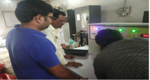
LIST OF EXPERIMENTS:
1. No load & blocked rotor tests on three phase squirrel cage induction motor.
2. Star Delta starting of three phase induction motor
3. Speed torque characteristics of three phase induction motor.
4. Load test on three phase induction motor
5. ‘v’ curve and inverted ‘v’ curve of synchronous motor.
6. Voltage regulation of three phase alternator by ZPF method.
7. Determination of direct axis and quadrature axis reactance of synchronous alternator.
8. Speed torque characteristics of capacitor start type 1-ϕ induction motor.
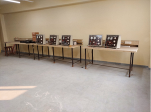
Course Objectives
• To understand the requirement of protection and their protection schemes.
• To understand the activities and attributes of different electromagnetic and static relays.
• To understand the working of different kinds of circuit breakers.
Course Outcomes
After the completion of this course the students will be able to:
• Understand the need and working of different types of switchgear equipment like circuit breakers and relays.
• Design the relay system according to the requirement.
• Application of various protection schemes of various power system components like alternators, transformers and bus-bars.
• Decision for various methods of protection in power systems.
List of experiments
1. To study the characteristics of Fuse and MCB.
2. To study the power measurement by using CT and PT.
3. To plot annual load curve and calculate average load and annual load factor from given data using MATLAB.
4. Study of Over Voltage Relay
5. To study the Over Current Relay.
6. To study the distance relay.
7. To study Differential Relay Protection.
8. Study of the Characteristics of Earth Fault Relay.
Course Objectives:
• To analyze the performance of power system networks by conducting various experiments.
• To study different power system protective equipment by conducting suitable experiments
• To address the underlying concepts & approaches behind analysis of power system network.
Course Outcomes:
At the end of this course, students will demonstrate the ability to-
• Acquire the concepts of power systems.
• Understand the various power system components.
• Evaluate fault currents for different types of faults.
• Understand the generation of over-voltages and insulation coordination.
• Analyse basic protection schemes.
List of Experiments:
1. Open circuit test on a single phase transformer.
2. Short circuit test on a single phase transformer.
3. Determine the characteristics of a differential relay protecting a transformer.
4. To study the principle of Circulating Current differential Relaying.
5. To study the performance of over voltage relay.
6. To study the performance of over current relay.
7. To study the performance of under frequency relay.
8. MATLAB program to simulate Ferranti effect.
9. To study power measurement using CT/PT.

